Robosapien Dissection
This page has moved, click here to be redirected.
<[ Main ] - [ Connection Details ]>
The following is photographs of a Robosapien dissection with some notes.

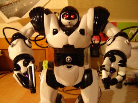
Robosapien prepares to be torn appart in the name of science.
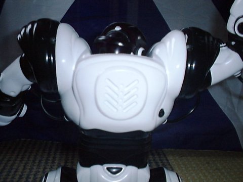
Four screws from the back and his chest and back will come off, careful with the back as the cable for the power switch and speaker needs to be unplugged from the PCB.
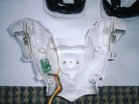
The back plate, showing the cable running to the switch and speaker.

Photo of Robosapiens main control board within his back. Note the two motors in the shoulders.
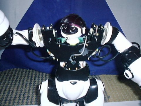
Underneath that chest there's not a lot. Potential space for adding your own hack such as my
robosapien alarm clock. You can see in the centre his microphone used for detecting 'sharp' noises such as tapping on his body or clapping.
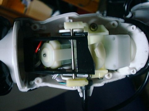
Within Robosapien's forearm is the motor which controls his elbow movement and also opens his hand when the elbow is fully rotated. The black piece at the front of the picture actuates the hand when it is pushed by the cam on the right hand side of the image. From the bottom feeds the black cable which feeds power to the motor and carries the data from the button on the end of his finger and also a limit switch located just out of sight in this picture.
For details of how the hand works see the LED mod page.
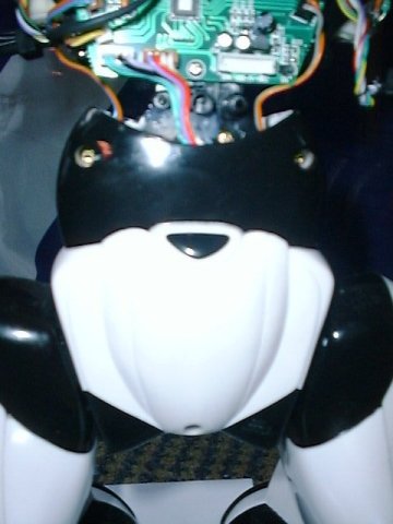
Three screws hold the lower torso bodywork on, the top two are covered with small caps but these are easily removed.

The two motors that control Robosapien's legs are clearly visable in this image. Also in there somewhere is the seventh motor which controls the sideways sway of robosapien which allows him to walk.

Robosapien from the front without any of his torso bodywork.
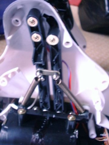
Taking the two side panels of his right foot you can see the two-bar link which keeps Robosapien's feet parallel to the floor whether his foot is infront or behind his body.

The various bodyparts taken off.

A word of caution, the forearms are actually glued together and some force may be required to seperate the two halfs. I noticed that two locating pins were snapped off while I tried to open it.
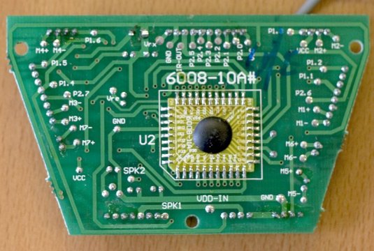
Better photo of the underside of robosapien's control board. Points to note are the solder pads designed to give us hackers easy access. On the other robosapien page of this website you can find a description of what each pad controls / is connected to.
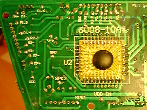
Took a while for me to get a decent picture, as I haven't set up the tripod and don't know the focal distance at which the macro setting on my camera is. Anyway, this is the underside of the Robosapien control board, as you can see there are solder points designed for us hackers to tap into an i/o line. We can see along the left of the photo the points for right arm and leg. At the bottom left of this picture is the connection to the speaker and the on/off switch. At the top left we see the right shoulder and along the top centre we see the head connection with the LEDs for the eyes and the IR receiver.
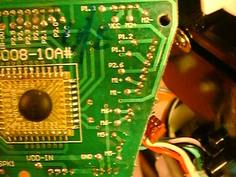
The "left" half of the control board underside (this connects to the left arm, leg and to the batteries).
For details on changing the leds in robosapien's hand see the LED mod page.
Related Links
The Robosapien Companion: Tips, Tricks, and Hacks (Technology in Action)
- featuring one of my photos!
- See the "Insider" pages of this site for more photos of Robosapien with his shell off:
http://i-cybiehot.com/robosapien/rbotinfox.html [no longer available] - For even more photos (showing details I didn't) visit http://zodiak.f2o.org/extra.php?id_extra=23 [no longer available]
Disclaimer

Except where noted otherwise these Photographs are licenced under a Creative Commons Licence.
Robosapien, Robosapien V2 & Roboquad are trademarks or registered trademarks of WowWee Group Limited.
I accept no responsibility or liability for anything you do. You may dismantle, alter or modify your Robosapien/RobosapienV2/Roboquad at your own risk.


