My Robosapien Hacking
This page has moved, click here to be redirected.
<[ Hack page 2 ] - [ Hack page 4 ]>
Stage 3: Robosapien Alarm Clock
While working on my robosapien hacking I came up with the idea of using it as an alarm clock. A piece of stripboard was cut to fit inside robosapien's chest cavity and was populated with an LCD (to display the time and any other information) and two PICmicros (one to concentrate on the clock timing/display and the other to interface with the robosapien's IR).
As the intention was to leave the Robosapien on 24/7 I added a socket in robosapien's back along with a DPDT switch to allow robosapien to be powered by a mains adapter. On one occasion I accidentally left the mains adapter at 9v (required voltage for the PIC programmer) and as a result fried robosapien's brain. I was able to obtain a replacement PCB from Wowwee and continue the project.
Photos
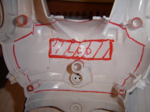
In order to add an LCD within robosapien's chest (for the Robosapien Alarm Clock) I used a dry-wipe pen and marked the depth I had to play around with (This is the max depth which can be used by the PCB (stripboard in my case), components and the LCD panel).

Using a Black & Decker Wizard (similar to dremel) I cut out the hole for the LCD panel. In this photo you can also see the yellow light from RS's microphone holes, this is an LED which is simply used for debugging.
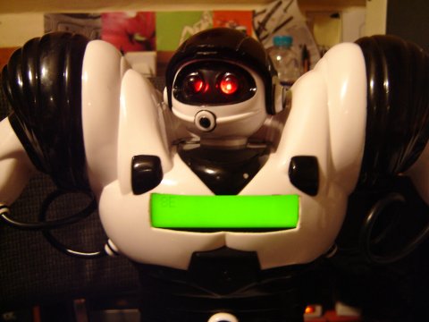
The LCD powered up and displaying the hex code for STOP. The backlight is a bit on the bright side in this photo but this was fixed with a resistor.
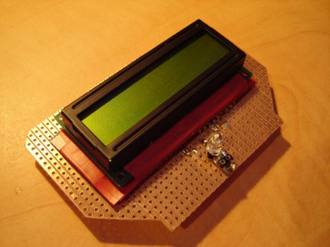
The stripboard with the LCD and an LED on the front.
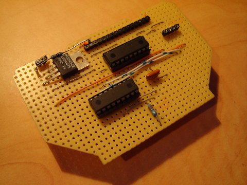
And the back of the stripboard with the voltage regulator (7805) and the two PIC16F84A's. The 2-pin socket is used for the 9v battery and the 4-pin socket carries the robosapien's vcc, ground, IR-OUT (signal to the robosapien) and IR-IN (signal from the receiver in his head).
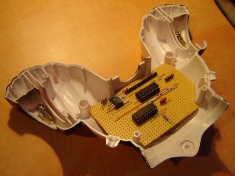
This shows how the stripboard fits in the back of robosapien's chestplate. This was done with a Black and Decker Wizard (similar to Dremel multi-tool) and a lot of patience. I trimmed off a bit here and a bit there until the board fit perfectly. Once I had a stripboard that fitted I started on the component layout.

Since the LCD needed a 5v supply I added a voltage regulator to the board and power it using a 9v PP3 battery. The 9V battery needed somewhere to go so I made a slot in his back above the speaker to accomodate the battery.
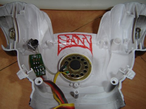
Inside view. I used a dry-wipe pen to mark out the material to be removed.

9V battery in the slot cut for it. This photo was taken before the AC/DC adapter socket was added.
Related Links
- www.robosapien.tk
- www.hackaday.com
- www.aibohack.com/robosap/
- home.comcast.net/~tomhandley/rs/rs.html
Disclaimer

Except where noted otherwise these Photographs are licenced under a Creative Commons Licence.
Robosapien, Robosapien V2 & Roboquad are trademarks or registered trademarks of WowWee Group Limited.
I accept no responsibility or liability for anything you do. You may dismantle, alter or modify your Robosapien/RobosapienV2/Roboquad at your own risk.


