Robosapien Circuit Diagrams
This page has moved, click here to be redirected.
<[ Hack page 4 ] - [ RS Components ]>
I have drawn the circuit diagrams for robosapien's PCB (Rev 6008-10A#). The numbers in square brackets are connections to another diagram (e.g. [ 5 ] would connect to a component on diagram 5). Also, the numbering system for the chips U2 and U3 is my own and should possibly start at the bottom left corner.
These drawings are not fully complete in places and may contain errors.
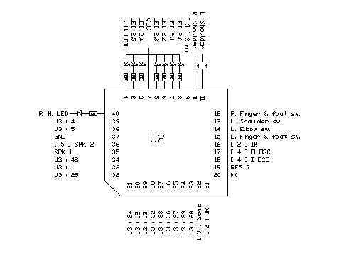
Diagram 1A, controller U2

Pin-out for the main controller U2.
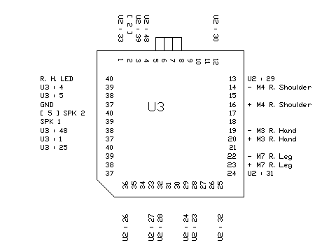
Diagram 1B, motor controller U3

Pin-out for the motor driver chip U3. Diagram is missing some connections which are either under the chip or are not connected.
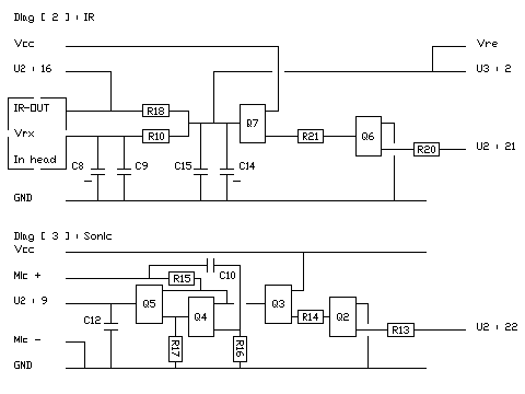
Diagrams 2 + 3, Infra-Red and sonic sensor

In Diag 2 we have the Infra-red receiver, which is mounted in robosapien's head.
Diag 3 shows the circuit associated with the microphone that is used to detect sharp sounds such as tapping on robosapiens shell or clapping.
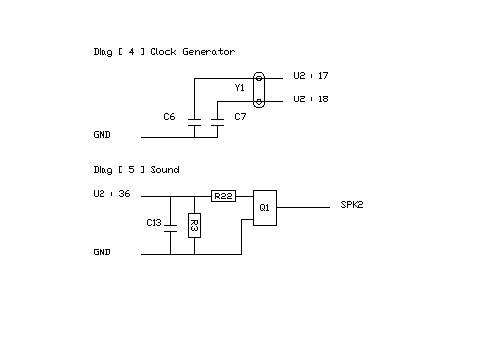
Diagrams 4 + 5, Clock generator and sound amplifier

Diagram 4 is the crystal used by U2 to provide it's clock pulse.
Diagram 5 connects the sound output of U2 to the speaker.
Components list
On the next page is a list of the resistor values, capacitor values (only electrolytic at the moment) and the markings of the Q components (transistors).
Omitted details
- Diagram of the power switch.
- Diagram of the power regulator circuit.
- Details of the foot/finger switches.
- Diagram showing the connectors and where they go.
- A full diagram showing everything together.


